ASIC Registers
The ASIC Register section of the Register window displays the current values of Amstrad Plus registers on the ASIC.
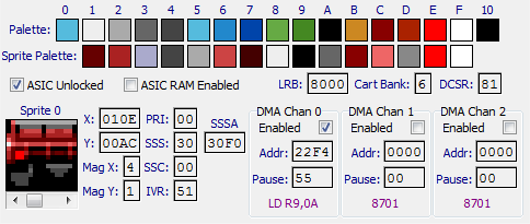
The registers are:
| Palette | The palette registers. These are the colours used for inks 0 to 15 (0 to #F) and the border (#10). Move the mouse cursor over the colour square to see the RGB (Red, Green and Blue) values for the colour. |
| Sprite Palette | The sprite palette registers. These are the colours used for inks 1 to 15 (1 to #F) in sprites. |
| ASIC Unlocked | Displays a tick mark if the ASIC has been unlocked. |
| ASIC RAM Enabled | Displays a tick mark if the ASIC RAM is enabled. |
| LRB | Lower ROM Base Address. Shows the mapped base address for the lower ROM. |
| Cart Bank | Shows the cartridge bank used for the lower ROM. |
| DCSR | DMA Control/Status Register. |
| Sprite | Shows an image of the selected Sprite. Use the scroll bar to select a sprite (0 to 15) |
| X | The X position of the selected sprite. |
| Y | The Y position of the selected sprite. |
| Mag X | The magnification factor for the width of the selected sprite. |
| Mag Y | The magnification factor for the height of the selected sprite. |
| PRI | Programmable raster interrupt scan line. If this is non zero an interrupt will occur when the value VCC * 8 + VLC equals this value. |
| SSS | Split Screen Scan. If this is non zero, a split screen will occur after VCC * 8 + VLC equals this value. |
| SSSA | Split Screen Start Address. The base address for the second screen in a split-screen. |
| SSC | Soft Scroll Control. |
| IVR | Interrupt Vector. Controls the vector supplied to mode 2 (IM 2) Z80 interrupts. |
| DMA Chan n | Shows information for each DMA Channel. |
The DMA Channel information is as follows: | |
| Enabled | Displays a tick mark if the DMA channel is enabled. |
| Addr | The address from which to get the next DMA instruction. |
| Pause | The pause value for the DMA channel. |
The purple value at the bottom is the next instruction to be executed. Moving the mouse cursor anywhere over the DMA Channel box will display the current pause counter, loop start address and loop count.